Elevator Installation Steps are among the most technically complex operations in modern construction. Unlike standard building systems, an elevator integrates structural engineering, precision mechanics, high-voltage electrics, and digital control logic all within a confined shaft, often while the building is still occupied or under active construction.
A systematic approach is not merely best practice it is a safety imperative. A single misaligned guide rail, an under-specified power circuit, or an incorrectly calibrated safety interlock can result in equipment failure, costly rework, or, in the worst case, injury to building occupants.
Hard System Authority
With over 10 years of experience operating in the specific construction environment of Damascus, Hard System has developed a repeatable, auditable installation methodology. We have navigated Syria’s regulatory landscape, adapted international EN 81-20 standards to local structural realities, and engineered solutions for the power and environmental conditions unique to this region.
This guide provides a transparent walkthrough of everything a client should expect from the first site visit to the day the elevator passes its municipal inspection and enters service.
Phase 1: Pre-Installation & Site Preparation
This is the most critical phase of all elevator installation steps. Errors identified here cost hours to correct; errors that pass undetected can require structural rework measured in weeks. Hard System’s Pre-Pour Audit protocol was developed specifically to address the tolerance variations common in Damascus masonry and reinforced concrete construction.
Shaft & Pit Inspection
Before any equipment is ordered or fabricated, a full physical survey of the elevator shaft is conducted against the requirements of EN 81-20:
- Plumbness (vertical alignment): Digital laser plumb systems verify that shaft walls are within ±2mm over the full shaft height.
- Pit depth: Confirmed against the equipment specification to ensure the buffer and safety gear have adequate clearance during emergency stops.
- Overhead clearance: The distance from the top-of-car to the shaft ceiling is measured and verified to allow for the car’s run-by and the required inspection clearance.
- Sump condition: The pit is checked for water ingress, drainage provision, and structural integrity before waterproofing or tanking is specified.
The Hard System Pre-Pour Audit
Damascus construction commonly uses locally sourced aggregate and variable-specification reinforcement. Our Pre-Pour Audit is a dedicated site visit before the machine room or pit slab is poured. We verify reinforcement bar placement, blockout sizes for guide rail brackets, and penetration coordinates for cables and conduits. Errors caught at this stage carry zero cost to correct. After the pour, correction requires cutting, patching, and potential re-engineering.
Power Requirements
All power infrastructure must be established before mechanical components arrive on site. This includes:
- 3-phase power supply at the correct voltage and frequency, confirmed by measurement, not assumption.
- A dedicated circuit breaker and isolator sized to the motor’s full-load current plus a safety margin.
- Conduit routes and cable trays mapped and installed to avoid future conflicts with mechanical components.
- Earthing and bonding to the shaft steelwork verified as compliant with Syrian electrical codes.
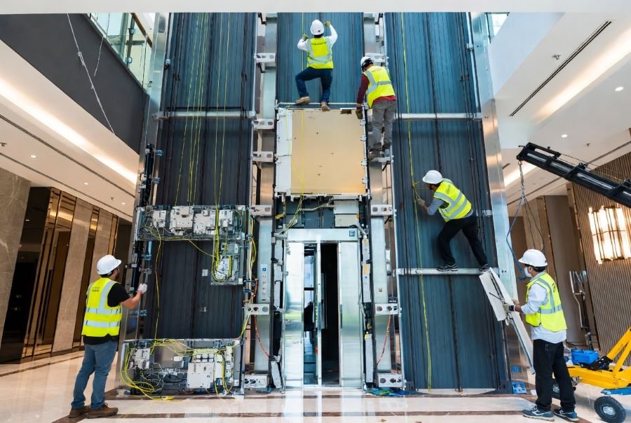
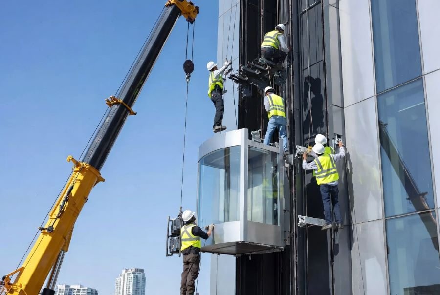
Phase 2: Mechanical Assembly & Structural Rigging
The mechanical assembly phase transforms a prepared shaft into the structural skeleton of the elevator system. Every alignment decision made here directly determines ride quality, noise levels, energy consumption, and the long-term reliability of the installation.
Guide Rail Installation
The guide rails are the backbone of the elevator. They define the precise vertical path of both the car and the counterweight, and their alignment is the single greatest determinant of ride quality. Hard System uses industrial laser alignment systems to verify straightness and parallelism within ±0.5mm per 5-metre section. Rail joints are filed and gauged to eliminate step transitions that cause vibration.
Brackets & Anchoring
Guide rail brackets are anchored to the shaft walls at intervals specified by the equipment manufacturer’s structural calculations. In Damascus, seismic load considerations require bracket fixings to be specified and installed to resist lateral forces beyond standard EN 81-20 requirements. All anchor bolts are torqued to the specified value and recorded in the installation log.
Car & Counterweight Assembly
The car frame is assembled in the pit and raised into position in sections where shaft access requires it. The counterweight frame is assembled on the opposite side of the shaft. Counterweight mass is set to equal the car dead weight plus 45–50% of the rated payload the balance point that minimises motor energy consumption over a typical duty cycle. Precise balance is verified by measuring current draw during up and down travel under no-load conditions.
Hoisting Machine Installation
The drive motor is installed either in a dedicated machine room at the top of the shaft or, for Machine Room Less (MRL) configurations, within the shaft headspace itself. Geared machines are aligned to the rope sheave using dial gauges; gearless permanent-magnet machines are aligned to the structural beam. Brake air gaps are set to the manufacturer’s specification and verified with feeler gauges. All values are recorded in the commissioning document.
Door Systems & Landing Entrances
Alignment
Landing door frames are set in the floor slab openings at each level and adjusted so that the landing sill is co-planar with the car sill when the car is level. A misalignment of more than 3mm creates a lip that causes passenger trips, degrades the car door drive coupling, and produces levelling errors that accumulate in service. Each floor is measured and documented individually.
Safety Interlocks
Landing door interlocks are safety-critical devices that prevent the landing door from opening unless the car is present and at floor level. Each interlock is tested individually: the door is manually held closed while the car is moved away, and the system is confirmed to prevent car movement. Each floor is tested and recorded as a pass/fail item in the commissioning certificate. No exceptions are accepted.
Phase 3: Electrical Wiring & Control Systems
The electrical and control phase is where a mechanical assembly becomes a functional elevator. The controller cabinet is the brain of the lift, interpreting calls, managing traffic, enforcing safety logic, and logging faults. In Damascus’s power environment, this phase carries additional engineering requirements not typically seen in more stable grid conditions.
Controller Cabinet & Travelling Cable
The controller cabinet is positioned to allow optimal travelling cable routing and to keep signal cables segregated from power cables throughout the shaft. Cable trays in the shaft are installed with a minimum 50mm separation between power and control wiring to prevent electromagnetic interference in the drive system. All cable terminations are labelled, sleeved, and crimped no bare-end connections are accepted.
Damascus Specialised Solutions: ARD & UPS
Power interruptions in Damascus are not an edge case they are a routine operational condition. Hard System treats the following as mandatory components on every installation, not optional upgrades:
- Automatic Rescue Device (ARD): On power failure, the ARD drives the car to the nearest floor on battery power and opens the doors, preventing passenger entrapment.
- High-capacity UPS/Battery backup: Sized to execute a minimum of three complete rescue cycles without grid power. The battery specification is reviewed against the local outage duration profile.
- Voltage stabilisation: Incoming supply is monitored and filtered to protect the variable-frequency drive from the voltage spikes common on the Damascus grid.
- Fault logging: The controller records all power events, enabling the maintenance team to correlate component wear with supply quality over time.
Wiring Standards
All wiring uses heat-resistant, fire-rated cabling compliant with Syrian safety codes and meeting EN 81-20 fire performance requirements. Travelling cables are specified with a minimum flex life of 1,000,000 cycles. No material substitutions are accepted regardless of supply chain conditions or cost pressure.
Phase 4: Testing, Commissioning & Safety Certification
The final elevator installation steps mark the transition from a static assembly to a certified, live transport system. Nothing is signed off until every measured parameter falls within its specified tolerance. Commissioning is not a formality it is the final verification layer that validates every decision made in the preceding three phases.
Load Testing
The elevator is loaded to 125% of its rated capacity the EN 81-20 minimum for brake and safety gear tests. Under this load:
- The overspeed governor is triggered manually to verify that the progressive safety gear engages and arrests the car within the allowable distance.
- The landing brakes are applied from full rated speed to confirm stopping distance is within specification.
- The buffer is compressed under controlled conditions to verify energy absorption.
- All structural connections are visually inspected after load testing for any signs of movement or deformation.
Ride Quality: Smoothness & Noise
Hard System uses calibrated measurement instruments to verify ride quality before handover:
- Accelerometers mounted to the car frame record vibration in all three axes during a full run. Peak and RMS values are compared against the Hard System Quality threshold (≤15 milli-g horizontal, ≤25 milli-g vertical).
- Decibel meters measure in-car noise at rated speed under load. Results are documented and provided to the client.
- Levelling accuracy is measured at each floor landing across multiple approaches from above and below.
Municipality Approval
Hard System manages the entire regulatory approval process with Damascus Municipality and the Ministry of Public Works. This includes preparation of the technical inspection dossier, scheduling of official inspector visits, attendance at all inspections, and resolution of any technical queries raised by the authorities. The client receives the original signed inspection certificate upon approval.
Handover & User Training
Client Education
Before the elevator enters service, the building manager and nominated maintenance contact receive a formal handover session covering:
- Emergency lowering procedure: Manual rescue operation to be used in the event of ARD failure.
- Daily monitoring checklist: Visual and audible indicators the operations team should check each morning.
- Fault code reference sheet: A laminated card fitted inside the controller cabinet door.
- Emergency contact procedure for Hard System’s 24-hour response line.
Maintenance Roadmap
A structured preventative maintenance schedule is agreed at handover. The schedule is tied directly to the manufacturer’s warranty conditions and is tailored to the duty cycle and environmental conditions of the specific installation. Standard intervals include monthly visual inspections, quarterly lubrication and adjustment, and annual safety gear and buffer checks.
Local Context & Damascus Challenges
Power Reliability
Damascus’s energy climate makes ARD and UPS systems mandatory infrastructure on every Hard System installation not optional extras. We size battery backup systems for a minimum of three full rescue cycles without grid power, and we specify voltage stabilisation as standard to protect variable-frequency drives from the supply transients that are routine on the local grid.
Environmental Factors
Syrian summers regularly exceed +40°C ambient temperature. Hard System sizes machine room cooling to maintain controller temperatures below the manufacturer’s maximum at peak ambient not average conditions. Controller enclosures are specified at IP54 or higher to address the fine construction dust prevalent during and after building works.
Regulatory Expertise
Hard System manages all permit submissions and regulatory approvals with the Damascus Municipality and Ministry of Public Works. We prepare the technical dossier, schedule inspector visits, attend all inspections, and manage the post-inspection documentation process through to issuance of the operating licence. Our client does not need to navigate this process we do it on their behalf.
Ready to Start Your Project?
Contact Hard System today for a site survey and technical consultation. We will walk your shaft, review the drawings, and deliver a no-obligation installation plan within 48 hours.